Zorlu Ortamları ve Topraklama Çubuklarının Rolünü Anlamak
Topraklama Sistemleri İçin Zorlu Bir Ortamı Belirleyen Nedir?
Topraklama sistemleri, toprak aşırı asidik veya alkali olduğunda (pH 5'in altında veya 8.5'in üzerinde), nem seviyeleri sürekli yüksek olduğunda ve özellikle kıyı bölgelerinde tuzlu hava ekipmanı etkilediğinde ciddi zorluklarla karşı karşıyadır. Sıcaklıklar ayrıca büyük oranda dalgalanabilir ve bazen eksi 40 derecenin altına düşebilir ya da 60 derecenin üzerine çıkabilir. IEC 62561 gibi standartlara göre toprak direnci 10.000 ohm metrenin üzerine çıktığında elektriksel direnç artar ve korozyon sorunları hızlanır. Fabrikalar ve endüstriyel tesisler genellikle iletkenlere daha fazla zarar veren kimyasalları toprağa boşaltırlar. Aynı zamanda çöl bölgeleri de kendi sorunlarını ortaya çıkarır çünkü topraklama çubukları gün boyu ve gece boyu yaşanan aşırı sıcaklık döngüleriyle defalarca genişleyip daralır ve birkaç ay süren maruziyetin ardından normal malzemeler nihayet bozulur.
Standart Topraklama Çubuklarının Aşırı Koşullarda Neden Başarısız Olduğu
Çinko kaplı çelik çubuklar, tuzlu toprak ortamlarına yerleştirildiğinde bakırla birleştirilmiş olanlara kıyasla en az dört veya beş kat daha hızlı bozulma eğilimindedir. Koruyucu tabaka her yıl yarım milimetre ile bir milimetrenin biraz üzerinde aşınır. Sıcaklıklar mevsimler boyunca sürekli dalgalandığında, bu metal çubuklar genellikle çatlar ve bu da elektrik dalgalanmalarına iyi dayanamayan zayıf bağlantılara yol açar. Donma noktasının yaygın olduğu bölgelerde başka bir sorun daha ortaya çıkar. Toprakta hareket eden kırağı, bu çubukları her yıl 15 ila 30 santimetre kadar yukarı itebilir. Bu kaldırma hareketi, çubuk ile toprak arasındaki önemli bağlantıyı bozarak, topraklama direncinin beş ohm'luk kritik eşiğin altında tutulmasını zorlaştırır.
Sistem Güvenliği ve Aşırı Gerilim Korumasında Topraklama Çubuklarının Kritik Fonksiyonu
IEEE'nin 2000 tarihli standartlarına göre, doğru şekilde kurulmuş topraklama çubukları yıldırım düştüğünde ekipman arızası riskini neredeyse %90 oranında azaltabilir. Bu çubuklar ayrıca elektrik arızaları sırasında dokunma ve adım gerilimlerinin kritik 50 voltluk eşik değerinin altında kalmasını sağlar. Daha da önemlisi, hassas elektronik cihazlara ulaşmadan önce bu tehlikeli gerilim dalgalanmalarının yaklaşık %95'ini yönlendirirler. Bunun düzgün çalışması için NEC Madde 250'de belirtildiği gibi toprak direnci 25 ohm'un altında olmalıdır. Geçen yıl bir sahil şantiyesinde korozyona dayanıklı topraklama çözümlerine geçtikten sonra yaşanan örneği ele alalım. Bakım giderleri yıllık neredeyse kırk iki bin dolar azaldı ve ayrıca tüm sezon boyunca beklenmedik kesinti yaşanmadı.
Topraklama Çubuğu Performansı İçin Temel Uluslararası Standartlar (IEC, IEEE, NEC)
IEC 62561: Yıldırımdan koruma sistemi bileşenleri ve topraklama çubuğu uygunluğu
IEC 62561 standardı, çeşitli endüstrilerde topraklama çubuğu malzemeleri ve yıldırımdan korunma sistemleri için uluslararası kurallar belirler. Bu standartlara göre, topraklama çubuklarının en az 1,5 metre uzunluğunda olması gerekir ve normal koşullara kıyasla korozyonun daha hızlı meydana geldiği tuzlu topraklarda bile yaklaşık 20 yıl korozyona dayanabilmelidir. Özellikle bakır kaplı çubuklar için, direnç değerini 10 ohm'un altında tutarken yaklaşık 300 amperlik darbe akımlarına dayanabilmeleri gerekmektedir. Bu gereksinimler, zaman içinde gerçek dünya koşullarını simüle eden özel hızlandırılmış yaşlanma prosedürleriyle test edilir. Güneydoğu Asya'nın bazı gibi yıldırım düşmelerinin sık görüldüğü bölgelerden elde edilen gerçek dünya verileri de önemli gelişmeler göstermektedir. 2023 Enerji Güvenliği Raporu'nda yayımlanan son bulgulara göre, bu bölgelerdeki tesisler, IEC uyumlu topraklama çözümlerine geçtikten sonra güç dalgalanmalarında yaklaşık %72'lik bir azalma yaşamıştır.
IEEE Std 80-2000: AC transformatör merkezi topraklamasında güvenlik için kılavuz
Bu standart, topraklama direncinin ayarlanması ve arıza akımlarının doğru şekilde hesaplanması gibi konuları kapsayan transformatör merkezlerinde topraklama çalışmasıyla ilgili güvenlik kurallarını belirler. IEEE sertifikalı topraklama çubukları için adım potansiyel gerilimi adı verilen bir üst sınır vardır. Bu değerler belirlidir: 50 Hz sistemlerde 5.700 volttan düşük, 60 Hz sistemlerde yaklaşık 6.650 volt olmalıdır. IEEE 80-2013'ün en son güncellemelerine göre, özellikle tuzlu hava nedeniyle malzemelerin zamanla aşındığı kıyı bölgelerine ekipman kurarken mühendisler, daha öncekine göre yaklaşık %20 daha büyük iletken kesiti kullanmalıdır. Bu ek önlem, bu zorlu ortamlarda güvenliği tehlikeye atan korozyonla savaşmada yardımcı olur.
NEC Madde 250: Topraklama çubuğunun yerleştirilmesi ve malzeme gereksinimleri
NEC tarafından zorunlu kılınan 2,4 m minimum çubuk derinliği ve üç onaylı malzeme kabul edilmektedir:
- Galvanizli çelik (en az 5,3 mm kalınlık)
- Paslanmaz çelik (Kalite 304 veya üzeri)
- Kaplamalı bakır çubuklar (en az 254 μm kaplama)
Tek bir çubuğun ≤25 Ω direnç değerine ulaşması gerekir (NEC 250.56); aksi takdirde ek elektrodlar gereklidir. Bu ihlaller geçen yıl endüstriyel elektrik kodu tespitlerinin %38'ini oluşturdu (OSHA 2024).
IEC, IEEE ve NEC topraklama çubuğu teknik özelliklerinin karşılaştırmalı analizi
| Standart | Toprak Tipi Odaklı | Korozyon Test Yöntemi | Maksimum Direnç |
|---|---|---|---|
| IEC 62561 | Kıyısal/Tuzlu | Tuz Püskürtme (ISO 9227) | 10 Ω |
| IEEE 80 | Genel | Alan Ölçümü | 5 Ω |
| NEC 250 | Ilıman | potansiyel Düşüşü 3 Nokta Yöntemi | 25 Ω |
NEC, galvanizli çeliğe izin verirken IEC bakır kaplı çubuklar gerektirir ve bu durum çok uluslu projeler için zorluk çıkarır. IEEE'nin transformatör merkezine özel kuralları, eşdeğer toprak koşullarında NEC'ye göre %40 daha derin gömme zorunluluğu getirir.
Zorlu Koşullarda Korozyon Direnci ve Ömrün Değerlendirilmesi
Toprak Özgül Direnci ve pH: Topraklama Çubuklarının Ömrünü Etkileyen Temel Faktörler
Toprak özellikleri doğrudan korozyon oranlarını etkiler. 5.000 Ω·cm'nin altındaki direnç, oksidasyon riskini %70 artırır (NACE 2023), pH seviyesi 4,5'in altındaysa bozulma hızlanır. Yüksek tuz içeriğine sahip kıyı bölgelerinin toprakları, kurak ortamlara göre topraklama çubuklarını üç kat daha hızlı aşındırır ve bu durum malzeme seçiminde lokasyona özel bir yaklaşım gerekliliğini vurgular.
Korozyon Hızlarının Ölçülmesi: ASTM G57 ve Diğer Alan Test Yöntemleri
ASTM G57 standardı, dört nokta toprak direnci ölçümlerini ve numune maruziyet çalışmalarını kullanarak korozyon değerlendirmesini standardize eder. Son zamanlarda çevre test odalarında yapılan deneyler, altı ayda kıyı bölgelerinde 10 yıla eşdeğer maruziyet simüle etti ve galvanizli çubukların yıllık 0,25 mm kaybettiği, bakır kaplı alternatiflerin ise yıllık 0,08 mm kaybettiği gösterildi.
Çevresel Maruziyete Göre Beklenen Kullanım Ömrü Hesaplamaları
| Çevresel Faktör | Hizmet Ömrü Çarpanı |
|---|---|
| Düşük tuzluluk (<500 ppm) | 1,8× temel değer |
| Yüksek nem (>%80 RH) | 0,6× temel değer |
| Asidik topraklar (pH 3-5) | 0,4× temel |
Bu çarpanlar, mühendislerin sert kıyı bölgelerinde tipik olarak 30 yıllık tasarımlar için beş yılda bir muayene aralıklarını ayarlamalarına yardımcı olur.
Sektörün Paradoksu: Yüksek İletkenlikli Malzemeler vs. Uzun Ömürlü Dayanıklılık
Saf bakır mükemmel iletkenlik sunar (101% IACS), ancak asidik topraklarda mekanik dayanım ve hibrit korozyon direnci nedeniyle bakır kaplı çelitten daha düşük performans gösterir. Tasarımcılar, NEC 250.52 iletkenlik gereksinimleri ile IEC 62561 dayanıklılık standartları arasında denge kurmak zorundadır; bu zorluk, iletken kaplamaların ve feda edilebilir anotların birleştirildiği katmanlı koruma ile en iyi şekilde çözülür.
Bakır Kaplı ve Galvanizli Çelik Topraklama Çubukları: Performans ve Yönetmelik Uyumu
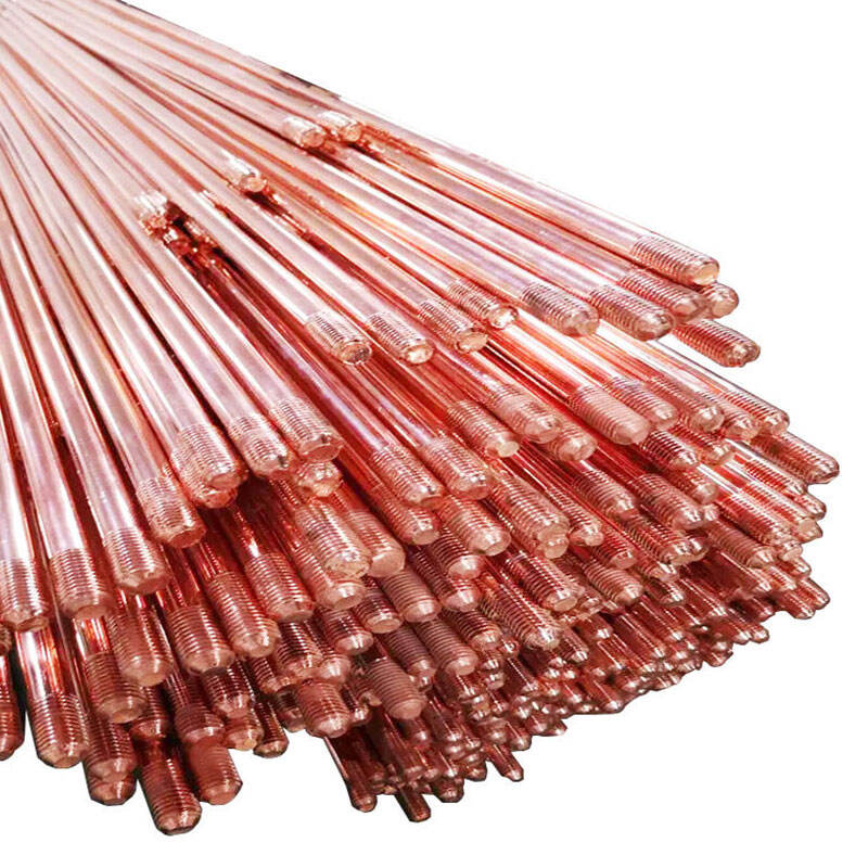
Bakır kaplı topraklama çubuklarının yapısı ve kaplama süreci
Bakır kaplı çubuklar, neredeyse saf bakırın moleküler düzeyde bir çelik çekirdeğe sürekli elektrokaplama teknikleri kullanılarak bağlandığı üretim yöntemleriyle üretilir. Bu işlem, yaklaşık 10 mil kalınlığında (yaklaşık 254 mikrometre) hem fiziksel aşınmaya hem de sert çevre koşullarına dayanabilen dayanıklı bir kaplama oluşturur. Geleneksel kaplama yöntemleri zamanla sıkça soyulurken, bu yeni nesil ürünler çok daha iyi yerinde kalır. Bakırın çelikle kaynaşma şekli, korozyona maruz kaldığında bile iyi elektrik iletkenliği sağlar ve bu yüzden IEC 62561 kurallarında belirtilen endüstriyel standart kalınlık spesifikasyonlarını karşılar.
Nemli ve tuzlu ortamlarda galvanizli çelik çubukların performansı
Kıyı bölgelerinde, galvanizli çubuklar sekiz yıl içinde çinko kaplamalarının %50-70'ini kaybeder. pH < 5 olan topraklarda veya klorür seviyesi 500 ppm'nin üzerindeki ortamlarda korozyon hızları, bakır kaplı çubuklara göre üç kat artar ve ortalama kullanım ömrü 15 yıla düşer; bu değer, bakır kaplı sistemlerin 40 yıllık ömrünün yarısından azdır.
Kod kabulü: Neden bakır kaplı çubuklar IEEE ve IEC uygulamalarında hakimdir
IEEE Std 80-2000, arıza anında sabit empedans nedeniyle transformatör merkezleri için bakır kaplı çubuk kullanımını önerir. NEC galvanizli çeliğe izin verse de, IEC 62561 sertifikalı sistemlerin %78'i bakır kaplı yapı kullanmaktadır (UL 2023 verileri). Bakırın kendini pasifleştiren oksit tabakası, direncin on yıllar boyunca 25 Ω'nun altında kalmasını sağlayarak uzun vadeli uyumunu destekler.
Maliyet-fayda analizi: Galvanizli alternatiflere kıyasla bakır kaplı ürünlerin uzun vadeli değeri
Bakır kaplı çubuklar başlangıçta %30-40 daha pahalı olsa da, 2,6 kat daha uzun dayanır ve 40 yıl boyunca çubuğa başına 1.200 ABD doları tasarruf sağlar. Ulusal Elektrik Topraklama Araştırma Projesi'ne göre bakır kaplı sistemler yıllık maliyetleri %58 daha düşük seviyede tutar. Kritik altyapılar için bu ömür, özellikle galvanizli çubukların üç yılda bir bakım gerektirdiği korozyona açık ortamlarda, başlangıçtaki yatırımın haklı çıkarılmasını sağlar.
Gerçek Dünya Dersleri: Kıyı Kurulumlarında Topraklama Çubuğu Arızasına İlişkin Vaka Çalışması
Arka Plan: Güneydoğu Asya Kıyı Trafo Merkezlerindeki Enerji Tesisi Arızaları
Güneydoğu Asya'daki sekiz kıyı trafo merkezinin 2022 yılında yapılan denetiminde beş yıl içinde dört tesisde topraklama arızaları tespit edildi. Aşırı gerilim koruması tutarsızdı ve toprak-çubuk direnci IEEE Std 80-2000 güvenlik eşiğini %37-58 oranında aştı.
Temel Neden: Yetersiz Korozyon Direnci ve Uyumlu Olmayan Malzemeler
İnceleme analizi iki temel sorunu ortaya koydu:
- Malzeme bozulması : Tuzlu toprakta (pH 8,1–8,5) galvanizli çelik çubuklar yılda 0,8–1,2 mm oranında korozyona uğradı ve bu değer ASTM G57 kıyaslama değerinin üç katıdır
- Uyumsuzluk : 8 sahanın sadece 2'sinde IEC 62561 sertifikalı çubuklar kullanıldı; başarısız olan birimlerin %85'inde bakır kaplama bağlantısı yoktu
Arızadan Sonra Düzeltici Müdahale: IEC 62561 Sertifikalı Bakır Kaplanmış Çubuklara Geçiş
Düzeltici müdahale, hem IEC 62561 hem de NEC Madde 250 ile uyumlu 48 adet bakır kaplı çubuğun yerleştirilmesini içeriyordu. Kurulum sonrası sonuçlar şöyledir:
| Metrik | Değişim Öncesi | Değişim Sonrası | Geliştirme |
|---|---|---|---|
| Toprak direnci (Ω) | 112 ± 18 | 28 ± 4 | %75 ↓ |
| Korozyon hızı | 1.05 mm/yıl | 0,12 mm/yıl | %89 â |
| Aşırı gerilim dağılımı | %78 verim | %99,2 verim | %21 â |
Dersler: Alçak Gerilim Topraklama Çubukları Standartlarıyla Satın Almayı Uyumlaştırma
Takım, tüm topraklama bileşenleri için zorunlu IEC 62561 doğrulamasını uyguladı ve bu sayede sonraki kıyı bölgelerinde yapılan kurulumlarda erken arıza riskini %94 oranında azalttı (2024 işletme verileri).
SSS
zorlu ortamlarda topraklama çubukları için karşılaşılan zorluklar nelerdir?
Zorluklara yüksek oranda asidik veya alkali topraklar, yüksek nem seviyesi, tuzlu hava, aşırı sıcaklık dalgalanmaları, yüksek toprak direnci ve kimyasal kirlilik dahildir.
2. Standart topraklama çubukları neden aşırı koşullarda başarısız olur?
Aşırı sıcaklıklarda ve tuzlu ortamlarda daha hızlı aşınma, çatlama, zayıf bağlantılar ve don hasarı nedeniyle başarısız olurlar.
3. Topraklama çubuklarının sistem güvenliğindeki önemi nedir?
Doğru şekilde monte edilen topraklama çubukları, yıldırım darbeleri sırasında ekipman arızası riskini neredeyse %90 oranında azaltır ve güvenli voltaj seviyelerinin korunmasını sağlar.
4. Topraklama çubuğu performansı için temel uluslararası standartlar nelerdir?
Temel standartlar IEC 62561, IEEE Std 80-2000 ve NEC Madde 250'dir.
İçindekiler
- Zorlu Ortamları ve Topraklama Çubuklarının Rolünü Anlamak
-
Topraklama Çubuğu Performansı İçin Temel Uluslararası Standartlar (IEC, IEEE, NEC)
- IEC 62561: Yıldırımdan koruma sistemi bileşenleri ve topraklama çubuğu uygunluğu
- IEEE Std 80-2000: AC transformatör merkezi topraklamasında güvenlik için kılavuz
- NEC Madde 250: Topraklama çubuğunun yerleştirilmesi ve malzeme gereksinimleri
- IEC, IEEE ve NEC topraklama çubuğu teknik özelliklerinin karşılaştırmalı analizi
- Zorlu Koşullarda Korozyon Direnci ve Ömrün Değerlendirilmesi
-
Bakır Kaplı ve Galvanizli Çelik Topraklama Çubukları: Performans ve Yönetmelik Uyumu
- Bakır kaplı topraklama çubuklarının yapısı ve kaplama süreci
- Nemli ve tuzlu ortamlarda galvanizli çelik çubukların performansı
- Kod kabulü: Neden bakır kaplı çubuklar IEEE ve IEC uygulamalarında hakimdir
- Maliyet-fayda analizi: Galvanizli alternatiflere kıyasla bakır kaplı ürünlerin uzun vadeli değeri
-
Gerçek Dünya Dersleri: Kıyı Kurulumlarında Topraklama Çubuğu Arızasına İlişkin Vaka Çalışması
- Arka Plan: Güneydoğu Asya Kıyı Trafo Merkezlerindeki Enerji Tesisi Arızaları
- Temel Neden: Yetersiz Korozyon Direnci ve Uyumlu Olmayan Malzemeler
- Arızadan Sonra Düzeltici Müdahale: IEC 62561 Sertifikalı Bakır Kaplanmış Çubuklara Geçiş
- Dersler: Alçak Gerilim Topraklama Çubukları Standartlarıyla Satın Almayı Uyumlaştırma
- SSS